Sound Intensity

Sound intensity is defined as the directional flow of sound energy per unit area (W/m2). Measuring intensity allows engineers to calculate the total sound power (LW) of a machine and is the most effective method for noise source identification in complex environments.

What is sound intensity?

In acoustic engineering, sound intensity (I) is a vector quantity defined as the time-averaged flow of sound energy per unit area (W/m2) in a specific direction. International standards such as ISO 9614 and ANSI S12.12 govern the modern technical application of these measurements for sound power determination and source localization.

The sound field is analyzed as a complex relationship between sound pressure and particle velocity. The active intensity (real part) represents the net flow of energy radiating away from a source, which is the primary metric for calculating sound power levels. The reactive intensity (imaginary part) describes the non-propagating energy typically found in standing waves or the extreme near-field, where energy oscillates without being radiated. Accurate measurement of these components requires a specialized intensity probe—usually a “p-p” (pressure-pressure) or “p-u” (pressure-velocity) configuration—paired with a dual-channel analyzer to calculate the phase relationship between the sensors.

natężenie dźwięku

Technical Characteristics of Sound Intensity

  • Vector Nature: Unlike sound pressure, which is a scalar (magnitude only), intensity indicates both the magnitude and direction of energy flow, allowing for the rejection of external background noise.
  • Active vs. Reactive: Active intensity measures energy that is actually “leaving” the machine, while reactive intensity identifies energy trapped near the surface or caused by reflections.
  • Measurement Indicators: The Pressure-Intensity (FpI) index is a critical technical indicator used to assess the accuracy of the measurement environment and determine if the background noise is too high for a valid test.
  • Surface Integration: To determine total sound power (LW), the intensity is measured over a defined virtual envelope (a “measurement surface”) surrounding the source and integrated over the total area.

What is sound intensity level?

In industrial and environmental acoustics, the Sound Intensity Level (LI) is a logarithmic measure used to describe the magnitude of acoustic energy flow. In reference to ISO 9614, the Sound Intensity Level is calculated using the following equation:

LI=10*log10(I/I0)

  • I: The measured sound intensity, representing the energy flow per unit area (W/m2)
  • I0: The standard reference sound intensity, defined as 1 pW/m2
  • Unit: The result is expressed in decibels (dB)

Relationship to Human Hearing

The human auditory system possesses a remarkable dynamic range, spanning approximately 12 orders of magnitude from the threshold of hearing to the threshold of pain. To manage this vast span, acoustics utilizes the logarithmic decibel (dB) scale, which compresses these intensities into a functional range of 0 to 120 dB. While the mathematical increments of the decibel scale are linear (e.g., 10, 20, 30 dB), human perception of loudness is highly non-linear. For instance, doubling the physical sound intensity results in a measurable increase of only 3 dB, yet most listeners require a 10 dB increase to perceive a subjective doubling of volume.
The standardized reference intensity (I0) represents the quietest sound a healthy human ear can typically detect at 1 kHz. At the upper end of the spectrum, the threshold of pain is generally cited at an intensity of 1 W/m2 (120 dB), though individual sensitivity and the duration of exposure can push this technical threshold toward 130–140 dB in some clinical cases. It is also important to note that auditory sensitivity is frequency-dependent and naturally declines with age, a phenomenon known as presbycusis, which primarily affects the detection of high-frequency sounds.

wyznaczanie poziomów mocy akustycznej

Why Measure Sound Intensity?

Sound intensity is measured to analyze the radiation characteristics of a sound source or to determine its total sound power, making it a primary tool for noise source identification. These measurements enable the creation of detailed sound field distribution maps by quantifying the directional flow of acoustic energy, typically measured in a direction perpendicular to the source. Unlike standard sound pressure level measurements, which only record the scalar magnitude of noise at a single point, sound intensity is a vector quantity that identifies both the magnitude and the specific spatial fragments where energy is radiating.

How to Measure Sound Intensity?

Sound intensity is measured using a specialized intensity probe, which typically consists of two phase-matched microphones separated by a fixed distance using a solid spacer (commonly 6, 12, or 50 mm). This configuration allows for the calculation of the pressure gradient, which is used to determine the particle velocity—the directional component of the intensity vector. For a valid assessment, a virtual measurement grid or surface is defined around the source, with the probe oriented perpendicular (orthogonal) to each grid segment to capture the normal component of the energy flow. The collected data is typically processed in one-third octave bands, providing a detailed frequency-dependent profile of the acoustic radiation.

A primary advantage of this technique is its ability to perform in-situ measurements in real operating environments, even in the presence of steady background noise or reverberation that would invalidate standard sound pressure tests. By integrating the measured intensity over the total surface area, engineers can directly calculate the sound power level (LW) of a machine. Furthermore, software allows these results to be visualized as intensity maps overlaid on photographs of the equipment, providing a clear graphical representation that pinpoints specific “hotspots” or components requiring noise mitigation.

jak zmierzyć natężenie dźwięku

What is a intensity probe?

In acoustic engineering, a sound intensity probe consists of a pair of phase-matched pressure microphones precisely aligned to capture the pressure gradient. To ensure international data defensibility, these systems must comply with IEC 61043 (Class 1) or the equivalent ANSI S12.12 standards. The microphones are typically arranged in a face-to-face (frontal) or side-by-side (parallel) configuration, separated by a fixed spacer. The size of the microphones determines the frequency range of the assessment; 1/4-inch microphones are required for high-frequency measurements (up to 10 kHz or more), while 1/2-inch microphones are utilized for lower frequencies due to their higher sensitivity.

The probe’s response must be phase-matched across the entire measurement spectrum to accurately calculate the particle velocity. These microphones are generally designed with a pressure response rather than a random-incidence (diffuse-field) response to maintain accuracy in the near-field of a source. When connected to a multi-channel analyzer or a Class 1 sound level meter, the system processes the signals into one-third octave bands, distinguishing between the active intensity (radiated power) and reactive intensity (stored energy). This dual-component analysis is essential for identifying “hotspots” on machinery and verifying the Pressure-Intensity (FpI) index to ensure the measurement environment is suitable for a valid test.

What is the significance of the distance between the microphones in the probe?

The spacer distance between the two microphones in a sound intensity probe is the critical factor determining the system’s operational frequency range. This distance must be precisely selected to balance two competing physical errors: finite difference error (at high frequencies) and phase mismatch error (at low frequencies).
To ensure international technical accuracy, the relationship between spacer size and frequency limits is defined as follows:

  • High-Frequency Limit (Finite Difference Error): As the wavelength of sound decreases, it becomes comparable to the distance between the microphones, leading to measurement inaccuracies. A 6 mm spacer is required for high-frequency precision up to 10 kHz. Increasing the spacer to 12 mm reduces the upper limit to 5 kHz, while a 50 mm spacer further restricts the accurate measurement range to approximately 1.25 kHz.
  • Low-Frequency Limit (Phase Mismatch Error): At low frequencies, the pressure difference between the two microphones is very small. To maintain a detectable signal-to-noise ratio and minimize phase errors, a larger separation is necessary. A 50 mm spacer is typically used for precision measurements down to 50–100 Hz, whereas a 6 mm spacer is generally unsuitable for frequencies below 250 Hz.
  • International Standards: These limits are strictly governed by IEC 61043 (Class 1) and ISO 9614. Exceeding these frequency thresholds results in a rapid increase in measurement bias, rendering the calculated Sound Power (LW) invalid.

How to determine sound power based on intensity?

Determining the Sound Power Level (LW) of industrial machinery often requires in-situ measurements because transporting large equipment to a controlled anechoic or hemi-anechoic chamber is impractical. Under international standards such as ISO 9614-1 (discrete points) and ISO 9614-2 (scanning), sound intensity measurements are the primary method for isolating a machine’s noise from the ambient background of a production floor.

The procedure begins by defining a virtual measurement surface (an “envelope”) that completely encloses the noisy machine. To ensure technical accuracy and data integrity, the following methodologies are applied:

  • Discrete Point Method (ISO 9614-1): The intensity probe is held stationary at specific nodes of a predefined grid. This is highly effective for detailed noise source localization and creating high-resolution “hotspot” maps.
  • Scanning Method (ISO 9614-2): The operator moves the probe at a uniform speed in a continuous path across the measurement surface. To verify the measurement’s repeatability and spatial averaging, the scan must be performed in two orthogonal directions—typically horizontal and vertical sweeps.
  • Accuracy Verification: If the difference in the measured sound power between the horizontal and vertical scan paths exceeds 1.0 dB, the measurement is considered invalid due to high field non-uniformity or inconsistent scanning speed. In such cases, the grid must be refined or the scanning procedure repeated to ensure a statistically valid result.
moc akustyczna

Determination of sound power levels based on sound intensity measurements in by ISO 9614-2

To determine the Sound Power Level (LW) ) of a source under real-world, in-situ conditions, the international standard ISO 9614-2 (and its equivalent PN-EN ISO 9614-2) specifies the scanning (sweep) method. This protocol requires moving an intensity probe at a uniform speed across a defined measurement surface to capture the normal component of the sound intensity vector—the energy flow strictly perpendicular to the virtual envelope. For a valid assessment, the noise source must remain stationary (stable) over the measurement duration, and the instrumentation must comply with IEC 61043 Class 1 requirements. A compliant technical report must document the average scanning speed, the Pressure-Intensity (FpI) index to verify background noise rejection, and the verification of repeatability between orthogonal scanning paths.

wyznaczanie poziomów mocy akustycznej norma iso9614

What does a noise map created using intensity methods look like?

The spatial distribution of sound intensity can be visualized by mapping measured data directly onto the geometry of the target machine or its surrounding environment. By applying color-coded contour maps to a 2D photograph or a 3D model, technicians can create an intuitive representation where “hotspots” identify the highest concentrations of acoustic radiation. This high-resolution source localization allows for the pinpointing of specific “acoustic leaks,” such as poorly sealed enclosures, vibrating panels, or unshielded exhaust ports, that may not be detectable through standard sound pressure measurements. Furthermore, modern 3D sound intensity software can render the energy flow as vectors, illustrating the exact direction and magnitude of noise propagation to guide the design of targeted noise abatement strategies.

Measurements of building partitions using in-situ stress methods

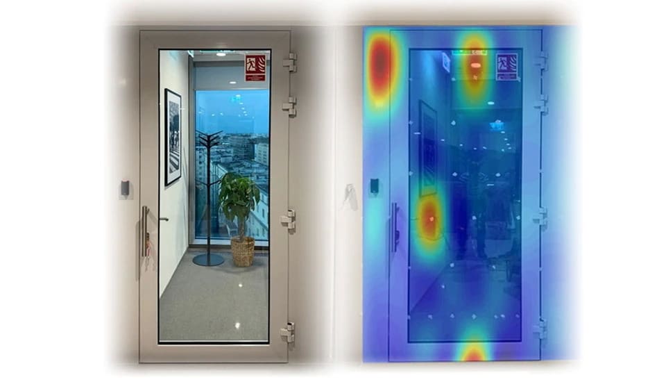
In building acoustics, the sound intensity probe is a highly effective tool for the in-situ evaluation of sound insulation and the performance of building partitions. By placing a calibrated sound source on one side of a structure (the “source room”) and scanning the intensity probe across the opposite face (the “receiving room”), engineers can measure the transmitted acoustic energy directly. This method is specifically utilized to pinpoint acoustic flanking paths and “leaks” that degrade the partition’s overall Sound Reduction Index (R). These sensitive points often include poorly sealed structural joints, service penetrations, or thermal bridges that act as significant conduits for noise.

Unlike standard sound pressure methods defined in ISO 16283, the intensity-based approach according to ISO 15186 allows for the isolation of specific segments of a partition even in the presence of high background noise. This high-resolution transmission mapping provides a precise graphical representation of where the partition’s acoustic integrity is compromised, allowing for targeted remediation rather than expensive, full-surface treatments.

Who can measure sound intensity?

In-situ and laboratory measurements of sound intensity must be performed by accredited acoustic testing laboratories staffed by qualified engineers. For example, the Svantek Research Laboratory provides specialized services for evaluating the sound insulation of building elements and partitions. These assessments are typically grounded in the ISO 15186 series, which utilizes the sound intensity method to determine the sound reduction index, even in the presence of flanking transmission or high background noise.

To provide a comprehensive technical report, the laboratory evaluates the partition’s performance across the standard one-third octave bands (typically 100 Hz to 5 kHz). The results are cross-referenced with ISO 717-1 to calculate the single-number quantity (RW) which allows for a direct comparison of the building element’s insulation properties against international building codes. These data are presented in both tabular and graphical formats, illustrating the frequency-dependent transmission loss and identifying any specific “acoustic leaks” or weak points in the structure.

pomiary przegród budowlanych metodami natężeniowymi

Request a Quote for Class 1 Noise & Vibration Monitoring Systems


    Please indicate the subject of your enquiry:

    I hereby consent to the processing of my personal data, i.e. my full name and e-mail address, by SVANTEK SP. Z O.O. with its registered office in Warsaw at ul. Strzygłowska 81 for the purpose of receiving marketing information on the products and services offered by SVANTEK SP. Z O.O. via electronic means of communication, in particular via e-mail, in accordance with the provisions of Article 10 sec. 1 and 2 of the Act on providing services by electronic means.

    I hereby consent to the processing of my personal data, i.e. my full name and phone number, by SVANTEK SP. Z O.O. with its registered office in Warsaw at ul. Strzygłowska 81 for the purpose of marketing activities with the use of telecommunications terminal equipment and automatic calling machines within the meaning of the Telecommunications Act.

    I hereby consent to receiving from SVANTEK SP. Z O.O. with its registered office in Warsaw at ul. Strzygłowska 81, via electronic means to the e-mail address I have provided, the newsletter and marketing information on the products and services offered by SVANTEK SP. Z O.O., within the meaning of the Act on providing services by electronic means.


    I declare that I have been informed that my data may be transferred to entities that process personal data on behalf of the Administrator, in particular to distributors - such entities process data on the basis of an agreement with the Administrator and exclusively in accordance with its instructions. In such cases, the Administrator requires third parties to maintain the confidentiality and security of information and verifies that they provide appropriate measures to protect personal data.

    Some of the entities processing personal data on behalf of the Administrator are established outside the EEA. In connection with the transfer of your data outside the EEA, the Administrator verifies that these entities provide guarantees of a high level of personal data protection. These guarantees stem in particular from the obligation to apply the standard contractual clauses adopted by the Commission (EU). You have the right to request a copy of the standard contractual clauses by sending a request to the Controller.

    I declare that I have been informed on my right to withdraw my consent to the processing of my personal data at any time, to access the provided personal data, to rectify, erase, restrict processing and object to the processing of my data, as well as the right to lodge a complaint with the President of the of the Personal Data Protection Office in the event of an infringement of the provisions of GDPR.