RT60 Reverberation Time

Reverberation Time (RT60) is a crucial acoustic parameter for rooms, representing the time it takes for sound energy to decrease by 60 dB after the sound source stops. It’s used to assess and optimize room acoustics for various purposes.

What is RT60 Reverberation Time?

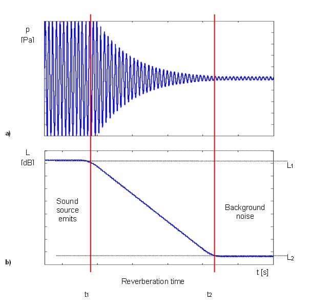
RT60 reverberation time is the main room acoustic parameter. Following ISO 3382, it is the duration required for the sound energy in a room to decrease by 60 dB after the source emission has stopped. The values of RT60 may range from fractions of a second to a few seconds and depend upon the size of the room and the nature of the materials used in its construction.

Following the Springer Handbook of Acoustics by Thomas D. Rossing, “reverberance is probably the best known of all subjective room acoustic aspects. When a room creates too much reverberance, speech loses intelligibility because important details (consonants) are masked by louder, lingering speech sounds (the vowels). For many forms of music, however, reverberance can add an attractive fullness to the sound by bonding adjacent notes together and blending the sounds from the different instruments/voices in an ensemble. The reverberation time T which is the traditional objective measure of this quality was invented 100 years ago by W.C. Sabine.”

Play Video about RT60 reverberation time

What is RT60 used for?

Reverberation time is used to determine the required acoustics for a room. The reverberation time RT60 in a room is determined by the absorptive properties of the reflecting surfaces and the distances between them. The purpose of this measurement is to obtain an objective, quantitative indication of the acoustic quality of a room in a building. In an empty room, sound waves reflect off of the walls, ceiling, and floor, and these reflections build up over time. This build-up of sound is known as reverberation, and it can be a major problem in large rooms with hard surfaces.

When designing a room for optimal acoustics, it is important to ensure that the reverberation time is appropriate for the intended use of the room. If the reverberation time is too long, the speech will be unintelligible and music will sound muddy.

On the other hand, if the reverberation time is too short, the room will sound sterile and uninviting. By carefully considering the absorption characteristics of the materials used in a room, it is possible to achieve ideal reverberation times for any given application.

Depending on the use of the room, more direct and less indirect (reflected) sounds are required. For example with a long reverberation time, a speech becomes less understandable and background noise levels increases,  and with a shorter reverberation time background noise reduces but voice muffles.

RT60 Reverberation Time Examples:

Type of room Reverberation time
Church2 – 10 s
Concert Hall1 – 2 s
Office 0.5 – 1.1 s
Classroom0.4 – 0.7 s

Measuring the change of Reverberation Time

Reverberation time can be used for calculating the amount of absorbent material required to achieve the desired room acoustics. In this approach, RT60 is measured first without the absorbent material in the room, and, then with absorbent material.

Formula for Reverberation Time

The volume and total absorption of a room have an impact on the reverberation time. The total absorption is obtained by summing the absorption of all the surfaces in the room, i.e. walls, ceiling, floor, and all the furniture. The absorption of each surface is the product of the area of the surface with its absorption coefficients. The absorption coefficients depend on the material and the frequency and the angle of incidence of the sound energy. 

Table of Contents

RT 60 example

The first graphs show RT60 reverberation time for a single frequency:

  • marker t1 indicates the moment when the sound source was switched off
  • the acoustic sound pressure decreases till the moment indicated by the marker t2

The bottom graph presents the decay curve:

  •  RT60 reverberation time value is equal to t2 – t1 when the difference between sound pressure levels L1 and L2 is 60 dB

What is a decay curve?

Following ISO 3382-1, the decay curve is a graphical representation of the decay of the sound pressure level in a room as a function of time after the sound source has stopped. It is possible to measure this decay either after the actual cut-off of a continuous sound source in the room or derived from the reverse-time integrated squared impulse response of the room. 

The decay directly obtained after non-continuous excitation of a room (e.g., by recording a gunshot with a level recorder) is not recommended for the accurate evaluation of the reverberation time. This method ought only to be used for survey purposes. The decay of the impulse response in a room is, in general, not a simple exponential decay, and thus the slope is different from that of the integrated impulse response.

RT60 reverberation time

Room acoustic parameter measurement according to ISO 3382-1

ISO 3382-1 describes a method for obtaining reverberation times from impulse responses and interrupted noise. It describes the measurement procedure, the information needed, and the methods of evaluating the data and presenting the test report.

RT60-Method of Interrupted Noise (Decay Method)

The RT 60 interrupted noise method obtains decay curves by directly recording the decay of sound pressure level after exiting a room with broadband or band-limited noise generated by a sound source. 

The time between markers ton and toff shows when the omnidirectional sound source emits acoustic power and a class 1 sound level meter measures the actual sound pressure level. The time between marker ttrig and te is the actual decay time measurement by the sound level meter. 

The decay method of RT 60 measurement requires an omnidirectional sound source that emits pink noise in the appropriate frequency band.

RT60 Method of Integrated Impulse Response (Impulse Method)

The RT 60 integrated noise method obtains decay curves by reverse-time integration of the squared impulse responses. This RT 60 measurement method requires an impulse sound source like a pistol, petard, or another sound source that emits impulse signals with a very high sound pressure level.

The time between markers ts and ttrig shows when the class 1 sound level meter awaits for the trigger condition to be met. The time between marker ttrig and te is actual decay time measurement by the sound level meter. 

This way of measuring sound decay was introduced first by M. R. Schroeder in two historical articles: New Method of Measuring Reverberation Time, Journal of Acoustical Societies of America, 1965 o Journal of the Acoustical Society of America, Vol. 66 (2), 1979, Integrated-Impulse Method for Measuring Sound Decay Without Impulses.

Impulse method RT60

What instrumentation is used for RT60 reverberation time measurement?

Following ISO 12683 to measure reverberation time RT60, a class 1 sound level meter meets IEC 61672 with octave filters meeting IEC 61260, and a sound source meeting ISO 3382 is required.

What is the sound source for RT60 measurements?

The sound source is an omnidirectional speaker that produces a sound pressure level sufficient to provide decay curves with the required minimum dynamic range without contamination by background noise. A minimum of two source positions shall be used. The height of the acoustic center of the source should be 1.5 m above the floor.

What signal is used for RT60 measurements?

For measurements of RT60 the broadband noise spectrum may be shaped to provide a pink spectrum of steady-state reverberant sound in the enclosure from 88 Hz to 5657 Hz. Thus, the frequency range covers the one-third-octave bands with mid-band frequencies from 100 Hz to 5 kHz or octave bands from 125 Hz to 4 kHz.

If only T20 is to be measured, it is sufficient to create a level at least 35 dB above the background level. If T30 is to be measured, it is necessary to create a level at least 45 dB above the background level in each frequency band.

EDT, RT20, and RT30-what are those?

EDT (Early Decay Time)

The EDT decay curve region is pointed out by markers t1 and t3. It is checked whether the selected decay curve region has proper dynamics for the EDT calculation:

L– L2 >= 10 dB 

L– L3 >= noise margin

It is recommended by the ISO-3382 standard to set a 10 dB value for noise margin.

In the case of the impulse method, the sound pressure level values between points t1 (with L1 level) and t2 (with L2) are approximated with the straight line (y = a · x + b) by the linear regression. Before approximation the EDT value is calculated using the slope coefficient ‘a’ according to the formula:

EDT = – 60.0 / a

In the case of the decay method, the EDT value is calculated according to the formula:

EDT= 6 · (t– t1)

EDT method RT60

RT20 (reverberation time calculated with 20 dB dynamics)

The RT 20 decay curve region is pointed out by markers t1 and t4. It is checked whether the selected decay curve region has proper dynamics for the RT 20 calculation:

L1 – L4 > 5 dB + 20 dB + noise margin

It is recommended by the ISO-3382 standard to set 10 dB value for noise margin.

In case of the impulse method, the sound pressure level values between points t2 and t3 are approximated with the straight line (y = a · x + b) by the linear regression. The RT 20 value is calculated using the slope coefficient ‘a’ according to the formula:

RT 20 = – 60.0 / a

In case of the decay method, the RT 20 value is calculated according to the formula:

RT 20 = 3 · (t3 – t2)

RT20 method RT60

RT30 (reverberation time calculated with 30 dB dynamics)

The RT 30 decay curve region is pointed out by markers t1 and t4. It is checked whether the selected decay curve region has proper dynamics to the RT 30 calculation:

L1 – L4 > 5 + 30 dB + noise margin

It is recommended by the ISO-3382 standard to set 10 dB value for noise margin.

In the case of the impulse method, the sound pressure level values between points t2 and t3 are approximated with the straight line (y = a · x + b) by the linear regression. The RT 30 value is calculated using the slope coefficient ‘a’ according to the formula:

RT 30 = – 60.0 / a

In case of the decay method, the RT 30 value is calculated according the formula

RT 30 = 2· (t3 – t2)

RT30 method RT60

How is the RT60 reverberation time measured?

Following ISO 12683-1, RT 60 is the time in seconds required for the sound pressure in a room to decrease by 60 dB after the sound source ceases. The keywords in this sentence explain that to measure reverberation time, a sound level meter and a sound source are used.

Source positions should be located where the natural sound sources in the room would typically be located. A minimum of two source positions shall be used. The height of the acoustic center of the source should be 1.5 m above the floor.

Following ISO procedures microphone positions should be at positions representative of the positions where listeners would normally be located. For reverberation time measurements, the measurement positions must sample the entire space. Microphone positions shall be at least half a wavelength apart, i.e. a distance of around 2 m for the usual frequency range. The distance between any microphone position and the nearest reflecting surface, including the floor, must be at least a quarter of a wavelength, or approximately one meter.

For reverberation time measurement, it can be useful to assess the materials of the boundary surfaces as well as any suspended elements in terms of their absorption coefficients and diffusion properties.

Is a difference of 60 dB practical?

When the 60 dB dynamic condition is difficult to obtain, the reverberation time (RT 60) is obtained using the slope coefficient of the decay curve. The type of the definition from which slope coefficient is calculated (EDT, RT 20, RT 30) depends on the difference between background noise level and sound source level. If the level difference is larger than 45 dB, the RT 60 parameter can be calculated using three definitions: EDT, RT 20, and RT 30. 

Standing sound waves method

The standing wave method uses a loudspeaker to produce standing waves in a tube with the testing material. The absorption coefficient can be determined by measuring the difference between the maximum and minimum sound pressures using a microphone that is moved down the tube’s axis. The standing waves method requires small samples of material but gives reproducible results. 

A standing wave is formed when acoustical energy is present in the system, a reflection takes place at the boundary surfaces, and the respective sound path equals the half-wavelength (the half-wavelength must fit between the boundary surfaces). 

Frequency bands RT60

Two methods of measuring the reverberation time are described in this part of ISO 3382: the interrupted noise method and the integrated impulse response method. Both methods have the same expected value. The frequency range depends on the purpose of the measurements. Where there is no requirement for specific frequency bands, the frequency range should cover at least 250 Hz to 2000 Hz for the survey (impulse) method. The precision method requires a frequency range from 125 Hz to 4000 Hz when measuring RT60 in 1/1 octaves. The range from 100 Hz to 5000 Hz is required for RT60 measurement in 1/3 octave. 

Use of the Integrated impulse response method

The impulse response from a source position to a receiver position in a room is a well-defined quantity that can be measured in a variety of ways (e.g. using pistol shots, spark gap impulses, noise bursts, chirps, or MLSs as signals).

The impulse source shall be able to produce a peak sound pressure level sufficient to ensure a decay curve starting at least 35 dB above the background noise in the corresponding frequency band. If T30 is to be measured, it is necessary to create a level at least 45 dB above the background level.

Special sound signals may be used that yield the impulse response only after special processing of the recorded microphone signal (see ISO 18233). This can provide an improved signal-to-noise ratio. Sine sweeps or pseudo-random noise (e.g. MLS) may be used if the requirements for the spectrum and directional characteristics of the source are fulfilled.

RT60 results

The evaluated reverberation times for each frequency of measurement shall be plotted in the form of a graph and stated in a table. The nominal mid-band frequencies for octave bands according to IEC 61260 should be marked on the frequency axis. A single figure reverberation time, T30mid can be calculated by averaging T30 in the 500 Hz and 1 000 Hz octave bands; T20, mid-ma, can also be used. Alternatively, take averages over the six one-third-octave bands from 400 Hz to 1,250 Hz.

Building Acoustics Assistant App

RT60 report

The test report should include the following information:

  • a statement that the measurements were made in conformity with this part of ISO 3382;
  • the name and location of the tested room;
  • a sketch plan of the room with a scale indication;
  • volume of the room—if the room is not completely enclosed, an explanation of how the room is not completely enclosed should be provided;
  • for speech and music rooms, the number and type of seats, e.g., whether upholstered or not, mid-May and if the seats are upholstered or not if the information is available, the thickness and kind of upholstery, the kind of covering material (porous or non-porous, raised, or lowered seats) and which areas of the seat are covered;
  • a description of the walls and ceiling’s shape and material;
  • the state or states of occupancy at the time of measurement, as well as the number of occupants;
  • the state of any variable equipment, such as curtains, a public address system, electronic reverberation enhancement systems, etc.
  • whether the safety curtain or decorative curtains were up or down in theaters;
  • a description of the stage furnishing, including any concert hall enclosure, if applicable;
  • the room temperature and relative humidity at the time of measurement;
  • a description of the measuring apparatus, the sources used, the microphones used, and whether tape recorders were used;
  • description of the sound signal used;
  • details of the source and microphone positions, preferably shown on a plan, together with the heights of the sources and microphones;
  • date of measurement and name of the measuring organization.
Building Acoustics Assistant App

Get a free PDF copy of the RT 60 article
Request more information on RT 60 meter.


    Please indicate the subject of your enquiry:

    I hereby consent to the processing of my personal data, i.e. my full name and e-mail address, by SVANTEK SP. Z O.O. with its registered office in Warsaw at ul. Strzygłowska 81 for the purpose of receiving marketing information on the products and services offered by SVANTEK SP. Z O.O. via electronic means of communication, in particular via e-mail, in accordance with the provisions of Article 10 sec. 1 and 2 of the Act on providing services by electronic means.

    I hereby consent to the processing of my personal data, i.e. my full name and phone number, by SVANTEK SP. Z O.O. with its registered office in Warsaw at ul. Strzygłowska 81 for the purpose of marketing activities with the use of telecommunications terminal equipment and automatic calling machines within the meaning of the Telecommunications Act.

    I hereby consent to receiving from SVANTEK SP. Z O.O. with its registered office in Warsaw at ul. Strzygłowska 81, via electronic means to the e-mail address I have provided, the newsletter and marketing information on the products and services offered by SVANTEK SP. Z O.O., within the meaning of the Act on providing services by electronic means.


    I declare that I have been informed that my data may be transferred to entities that process personal data on behalf of the Administrator, in particular to distributors - such entities process data on the basis of an agreement with the Administrator and exclusively in accordance with its instructions. In such cases, the Administrator requires third parties to maintain the confidentiality and security of information and verifies that they provide appropriate measures to protect personal data.

    Some of the entities processing personal data on behalf of the Administrator are established outside the EEA. In connection with the transfer of your data outside the EEA, the Administrator verifies that these entities provide guarantees of a high level of personal data protection. These guarantees stem in particular from the obligation to apply the standard contractual clauses adopted by the Commission (EU). You have the right to request a copy of the standard contractual clauses by sending a request to the Controller.

    I declare that I have been informed on my right to withdraw my consent to the processing of my personal data at any time, to access the provided personal data, to rectify, erase, restrict processing and object to the processing of my data, as well as the right to lodge a complaint with the President of the of the Personal Data Protection Office in the event of an infringement of the provisions of GDPR.

    svantek consultant

    An authorized SVANTEK consultant will help You with the details such as the required accessories for your noise monitoring task.

    processing...